


est. 1975
B & B Custom Circuits
Steve & JoAnna Barbato
Andover, NJ 07821
B&B TECH: A Tidbit Of Information On Fairbanks/Morse Magneto's- How do I Tell The Difference?
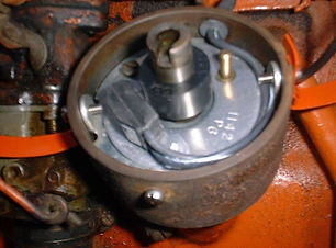
Ever wonder what those letters and numbers mean on the side of your Magneto? Believe it or not, they do actually mean something! Here's a little bit of info the next time you happen to see a Mag laying on a swap meet table for sale with numbers & letters stamped on it. Fairbanks/Morse always coded their Mags to the application their Mag was designed for. Let's take the popular FMJ4B3 Magneto found on quite a few Allis-Chalmers machines up to around 1950 or so.
The first two letters "FM" obviously mean "Fairbanks/Morse". That's the easy part. The next letter "J" or "X" is the model "series" of the Mag. The next digit "4" indicates the number of cylinders the Magneto was designed for. Moving to the next digit "B" means its a flange mount Magneto. (there were also base mount designed Mags) The last digit "3" was Fairbanks' customer code, which in this case was Allis-Chalmers. On some model Mags, you may see another digit at the end after the "3", such as an "A". (FMJ4B3-A) This means that particular Magneto has a specific modification for a certain AC engine, which again in this case was relocating the grounding lug to the opposite side of the Magneto's housing. Some early AC model Tractors like the WC as an example, had a rod connected to the steering column, which ran down to the Mag to ground the Mag and shut down the engine.
So there ya go, you learned a little bit more about that thing that's bolted to the side of your engine that makes spark to make your engine run. That thing will also make your hair stand up to if you get a little sweat or moisture between the spark plug wires and your fingers if you make the decision to straighten out the wires while the engine is running. Be careful! People who get zapped by a hot Magneto talk funny afterwards for a little while. Don't ask me why I know that.....
B&B TECH: One Wire Alternators vs Three Wire Alternators. What's the Skinny?

Left- One of our "SI" Alternators with our Quick Disconnect Diode Module plugged in.
Well, its pretty simple. One wire Alternators were designed to be a simple install for one, with just hooking up one wire, but they're not really what they're cut out to be against a Three wire Alternator even though they have a higher amperage rating. Let's examine this.
More and more people are moving to 12V wiring systems on their Tractors in lieu of the 6V OEM system. Reliability, more lighting, Battery Ignition, etc all have a big effect on the reason for the change-over. Installing a One wire Alternator on a Tractor isn't a bad thing, providing the Tractor doesn't have any lighting, or Battery Ignition to power up. (Distributor) If your Tractor is equipped with a Magneto, and no lights the One Wire will pretty much do the job has being the charger to keep the Battery up to snuff. Hooking the Alternator up directly to the Battery will keep the Battery topped off. That's fine for a real early Tractor with nothing on board. But, there's also another problem with a One Wire on a Tractor. One Wire Alternators need 1200-1400 RPM to "excite" the internal regulator in order to start the charging process. With early Tractor engines in general, they were designed to work in the cellar, meaning at low rpm's. Revving an older early Tractor engine to 1200-1400 rpm's makes it a bit tough on that engine, not to mention the extra wear factor of taking the engine to higher rpms that it isn't meant to work in. Who wants to put that kind of wear on the engine like that? Not me, that's for sure. There are a few ways to cut down on the rpm factor like installing a smaller pulley to spin the Alternator faster, but who wants to spend all that time hunting around for somethin' like that when you need to get the Tractor in the field to get some work done? You could spend a day just looking for something like that. Now, let's look at the Three Wire and the benefits it has.
Let's move ahead a few years and now our Tractor as Headlights, Taillights, a Distributor with Electronic Ignition, work lamps out back, and maybe a few other accessories like an auxilary power outlet. Hooking up a One wire Alternator the same way as the early Tractor isn't gonna cut it for the Tractor that has the extra accessories that need constant power, and that power needs to be monitored to satisfy the Battery as well as the components in the electrical system. Without a "sense" wire to the Voltage Regulator inside the One Wire, there is no regulation for the power being used. With the One Wire just hooked to the Battery, the Battery will have to feed the system with power. Although the One Wire has a Voltage Regulator inside, it will only charge as much as it can (around 14.2 volts) and maintain that 14.2 volts at the back of the Alternator. With other accessories now needing power, and drawing off the Battery, the One Wire will have a tough time keeping up to the power being pulled from the Battery. The end result, everything on board the Tractor will be running at a lower voltage, and depending on how much the draw is, could actually run the Battery and the system down! Also keep in mind, there is already a voltage drop between the One Wire's output post to the Battery through the output wire, and depending on how long that circuit is greatly effects voltage drop! This means the Battery itself may only be getting 11.5-12 volts! Not good! That Tractor could come in at the end of a work day with a low Battery, and may not start the next time its needed. Bring in the Three Wire
A Three Wire unit takes a little extra time to hook up, but the end result is a much better functioning system and for the components in that system. The two extra wires that make up the Three Wire system actually let the Alternator monitor the usage of power on board the Tractor as the accessories use that power. One of the wires that makes up the Three Wire system gets connected to the #1 terminal on the Alternators internal Voltage Regulator plug. This terminal runs to the key switch and is connected to the Ignition side of the key switch. When the key switch is turned in the ON position, 12V's is sent to the #1 terminal which "turns on" the internal Voltage Regulator. Now that the VR is turned on, there's no need to rev the snot out of the engine to get it to charge like you would have to do with the One Wire system. Hmmm.... there's an advantage right off the bat! Let's keep goin' here. The second wire that makes up the Three Wire system is the "sense" wire or "Voltage Sensing" circuit. On small systems, this wire can be jumpered to the output terminal at the back of the Alternator. This will monitor voltage being used on a smaller system and usually sustain the small system that may only have a few lights and a Battery Ignition. (Distributor) On larger Tractors, the voltage sensing circuit should be junctioned down stream where accessories are tied into the system. The Alternator can now monitor the system right where most of the load is being distributed throughout the Tractor. (usually around the dash area) The end result is now the Battery is satisfied, as well as the rest of the system because the Voltage Regulator is doing its job in monitoring the usage of power. Not only that, accessories and components are operating at peak voltage not at a lower voltage, the Battery stays full and ready for the next days work when it comes to jump up on the Tractor to fire it up again and put it back to work! Hey! That works for me too! There's nothin' worst than getting on your Tractor to put it to work again, only to find the Battery is dead, or to low to start the Tractor. Gotta jump start the Tractor again!! Sheesh! If you decide to convert your Tractor to 12 volts, take in consideration the advantage of a Three Wire system. Its only two more wires.....
B&B TECH: How To: Installing a Pertronix Electronic Ignition Kit In An Allis-Chalmers Model G
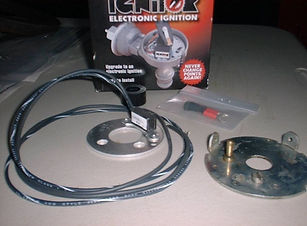
PERTRONIX ELECTRONIC IGNITION INSTALL
Tired of changing out points and condensers? Can't rely on that Chinese junk ignition components anymore? Then here's the hot ticket to take care of that stuff once n' for all! With a Pertonix electronic igntion, you'll have a faster starting engine, a smoother and better running engine, and the longevity and reliability of electronic ignition. No more points and condenser! Woo Hoo! Follow along with us on the "how to" install an electronic ignition. We were working on a customer's Model G equipped with the N62 Continental engine. This engine is equipped with a Delco Remy Distributor. There are a lot of different "E.I.'s" available for other makes of Distributors also. Follow along with us step by step, and we'll show you what to look for as you move along with your install.
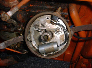
After removing the Distributor Cap, Ignition Rotor, & inner dust cover, the points and condenser were then in view to remove for our Electronic Ignition install. Also in this pic, we removed the rusty snap springs that hold the Cap down and in place. We'll take them for a visit to the glassbeader and get them all cleaned up for a re-install.
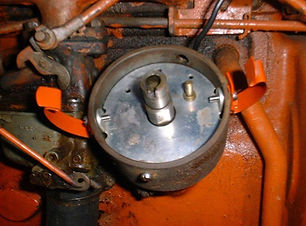
While we're at the breaker plate, it would be a good idea to remove the breaker plate via the three 8-32 machine screws to inspect the centrifical advance springs to make sure they're in good shape and not broken. The thin screwdriver points to one of the advance weight springs. These are in great shape, and the advance weights move nice and freely. Always check the side to side movement on these old Delco Distributor mainshafts. If you are able to move the mainshaft side to side more than .003-.005" thousands, the Distributor will need to be rebuilt. The Oilite bushings are probably worn allowing the mainshaft to wobble. This one was in nice shape, and no wobble was detected. If you find a broken spring, we have replacement spring sets in stock. Always replace the springs in a pair so they are matched.
With the cleaned up breaker plate re-installed, and the cap springs back from the glassbeader with a fresh coat of Orange applied, they are then re-attached to the outside of the Distributor housing. We're ready to install the new Electronic Ignition from Pertronix. Here comes the cool part! Woo Hoo! No more points and condenser!
The Pertronix electronic module and mounting plate drop right onto the stock breaker plate. Line up the holes, and it drops right in! Use the mounting screw that held the points in to anchor the electronic module and its mounting plate in place. It should look like this when the module is installed.
The OEM insulator block and fiber washer will no longer be needed. Pertronix's gives you this neat rubber grommet that needs to be installed on the E.I. module wires. This grommet slides down the wires through the hole in the Distributor housing where the OEM insulator block mounted in. The groove you see in the rubber grommet locks into the hole to make a nice seal to keep moisture and dirt out, and to protect the electronic modules wire's as they pass through the Distributor's housing. Notice one wire is all Black, the other is Black with a White Tracer. We'll be going over that when its time to wire this puppy up!
The OEM insulator block and fiber washer will no longer be needed. Pertronix's gives you this neat rubber grommet that needs to be installed on the E.I. module wires. This grommet slides down the wires through the hole in the Distributor housing where the OEM insulator block mounted in. The groove you see in the rubber grommet locks into the hole to make a nice seal to keep moisture and dirt out, and to protect the electronic modules wire's as they pass through the Distributor's housing. Notice one wire is all Black, the other is Black with a White Tracer. We'll be going over that when its time to wire this puppy up!
Next item to go in is the Magnetic pickup sleeve. This sleeve is designed to fit down over the mainshaft and align with the old points rub block cam. I turn this collar slowly till I feel it drop down over the cam. Then I know its aligned correctly. Push this collar down gently till it bottoms on the cam. Test fit your dust cover to make sure the dust cover fits flush without interfering with the magnetic sleeve. If the dust cover doesn't fit flush the way its supposed to, the sleeve isn't down all the way. Sometimes these magnetic sleeves are a tight fit at the bottom (which you want) so finger pressure isn't enough. I use a 5/8" socket and tap it down with the butt end of a screwdriver handle. As I mentioned, be gentle! Once the dust cover fits flush, you're good ta' go!
Our customer's old coil didn't ohm out correctly, so this old dude was in need of retirement. Makes you wonder how some of these old Tractors even ran with failing Ignition components. This coil looks like an older Ford style with the two posts close together to one another. If I didn't know better, I'd swear this was a 12V coil the way it ohmed out. Its time to press one of our B&B heavy duty 6V coils into service to add more "fire to the hole"....
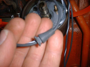
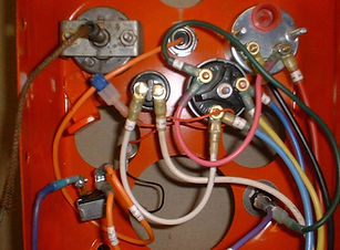
Steppin' up to the plate is one of our HD 6V Ignition coils. Because this is a 6V Positive Ground system, the wiring is done special according to the Pertronix instructions. Make sure you always read over the instructions first before installing a system like this. Keep referring back to it to double check your wiring! Pertronix encloses the instructions for a reason. Make sure you get yourself familiarized with them! On the 6V PG system, the plus (+) side of the Ignition coil needed to go to a good chassis or Battery ground. The wire with the spiral in it is the grounding circuit. Now, remember those two Black wires I mentioned earlier? The solid Black wire runs to the Ignition switch. The Black wire with the White tracer runs to the minus (-) side of the Ignition coil. Oh man! We're gettin' real close here! Always double check your wiring before energizing the system.
With everything in place, and making sure all wiring is clear of the rotating fan shaft that runs down the middle of the engine, I pulled out the Ignition switch, pulled on the starter rod and this ole' girl turned 1 1/2 revolutions and was sitting there running pretty darn nice! Even with a sour Carburetor that was over-fueling the engine. That's a whole other story. Once that nasty old Carburetor gets one of our super rebuilds, this little Model G is gonna purr like a kitten!! Hope this article helps you out with installing an electronic ignition, as well as helping you decide whether you want to install one. We sell quite a few of these units in our rebuilt Distributors, and in most cases, if one of our customer's installs and E.I. in one of his Tractors, he's usually calling us back to get another for his other Tractors! Hey, a 1940's Tractor with electronic ignition. Life is good...!
Steve Barbato Sr.
B&B TECH: Ammeters vs Voltmeters What's The Difference?
Well, there's quite a bit of difference. An Ammeter is considered a "flow meter". You have to run full voltage through it in order for it to tell you something. Ammeter's function fine and work quite well in systems that have a Generator downstream doing the charging chores. Because Generators are limited to what they can put out as far as "output", if an Ammeter is downstream, as long as the Generator's output is under the rated Ammeter, things will work as they should. But, bigger upgrades could cause problems. In comes the Alternator.
One of the most popular upgrades for Antique Tractor owners is the move from 6 volts to 12 volts. Upgrading the original 6 volt system enables faster starts, being able to incorporate more lighting on board the Tractor as well as other accessories. This actually brings an old antique Tractor into the more modern times. BUT.. not without a price. The easiest way to do this with most Tractor enthusiast's is to retire the old 6V Generator, and wiring system, and slam on a more modern Alternator that's equipped with an internal voltage regulator. Well, this is all well and good, but installing an Alternator and having an Ammeter downstream could be trouble! Let's examine this...
Modern Alternators are solid state inside. Their internal voltage regulators are very sensitive to load changes within the wiring system. These voltage regulators "sense" when something is turned on, or when voltage drops due to a load somewhere on board. The voltage regulator senses this, and immediately ramps the Alternator up to compensate for that particular load. Turn on a few more things, and again, the Alternator ramps up a bit and compensates for the continuing loads, also keeping the Battery happy at the same time. So, you kinda see what's going on here. Now, with an Ammeter downstream wired into the system and connected to the Alternator what happens if we get a short circuit on board the Tractor somewhere? If the Ammeter that's wired into the Alternator equipped system only has a 20/20, 30/30, or even a 60/60 sweep Ammeter, there could be trouble a brunin'. Something as simple as a wire pinched in one of the fenders, or a major circuit that may be rubbing on the torque tube or caught under a piece of sheetmetal that can cause a "short" or "load" can make things pretty dangerous on board that Tractor to the driver! As we said, as things get turned on, the "load" increases in the system. Now, this pinched or rubbed through wire starts a load. As I said, a load is a load no matter what it is and that sensitive voltage regulator inside that Alternator is picking up the load from the "sense" circuit. Now understand, most late model Alternators, even one that has a maximum "output rating" of say 35 amps, because of the solid state voltage regulator, and the capabilities of output that that Alternator can put out, can overcome a low sweep 30/30 or even a 60/60 sweep Ammeter if the load is heavy enough to make that Alternator "full field". A 35 amp Alternator full fielded is capable of putting out up to 50 amps or more in nano seconds! What happens to that Ammeter? Well, if the Ammeter is not designed for that type of load, smoke and flames are going to be the outcome. Why is that? Well, remember, we said an Ammeter is a "flow meter", and it needs full power run through it in order for it to tell you something. If you have an overload of that nature happen on board your Tractor to your Ammeter, the last thing you want out in the field is a fire! It should be telling you to get a fire extinguisher! Enter the Voltmeter...
A Voltmeter is not considered a "flow meter" like an Ammeter. A Voltmeter only "splices" into the electrical system and monitors whats going on with the system. As a matter of fact, a Voltmeter is about as simple as the Tractor! The only thing you need to know with a Voltmeter is where the proper charging range is. The normal charging range in all 12V systems is 13.9-14.5 volts. 14.2 being ideal. If the Voltmeter is reading below that normal charging area, the system is not charging. If its above 14.5 volts heading to 15 volts or higher, this immediately brings to the drivers attention that an overcharging issue is going on and the system needs to be looked at to see why this is happening. Pretty simple. The best part is, a Voltmeter is pretty darn accurate, so it can monitor the electrical system without there being a danger of fire. At least at the instrument panel. And lets face it, on most of these old time 30's,40's, and early 50's Tractors, the Ammeter is between your legs! Not a good place to have a fire start! Sooo, if that same type of short starts on board your Tractor, and there's a Voltmeter wired in, it will bring to your attention there's a problem somewhere on board, and it'll need to be addressed pronto! One of the many reasons why Detroit removed Ammeters from Automobiles starting in the late 70's and installed Voltmeters instead. Safety! That is the main reason why I do not build or offer our 12 volt Alternator systems with an Ammeter! SAFETY! Be safe. Be smart. If you're moving from 6 volts to 12 volts, and you decide to wire up your Tractor yourself, make sure you choose a Voltmeter, especially if your choice for the charging system is an Alternator! Nuff said!
B&B TECH: Delco Remy Alternators- The Popular "SI" Series Alternators What's The Difference?
One of the most popular Alternators ever to be used throughout the Automotive, Industrial, and Agricultural fields has got to be the ever popular Delco Remy "SI" series Alternator. From Forklifts to Hotrods, this Alternator is used in so many different applications it'll make yer' head spin!
First introduced to the Corvette line in 1969, the Delco "SI" series Alternator made its debut. It was available as an optional Alternator in the GM line of cars and trucks in 1970, 71, and 1972, however by 1973, most GM cars and trucks were equipped with the "SI" series Alternators as standard equipment on all engines. During those few early 70's year cars and trucks, the 10 "DN" series Alternators were the norm. Those particular units were used with an external Voltage Regulator to control current throughout the charging system.
Delco Remy's 10 "SI" Series Alternator (rear shot)
What The Heck Does "SI" Mean?
The "SI" stands for "System Integrated". Okay, what does that mean you ask? It means the Voltage Regulator is located inside the Alternator. With moving a solid state Voltage Regulator inside the Alternator, this made a more compact unit, which did not rely on an external Voltage Regulator to monitor the charging chores. It also cleaned up the engine compartment and also didn't let Mother Nature play havoc with the regulator anymore. This also equated to less wiring for Mother Nature to also play havoc with. All in all it was a big upgrade to GM's charging systems, and worked flawlessly for decades. These Alternators were available in several different output ratings. The windings inside the Alternator determined the available output. The early units were available with a 63 amp output as a maximum, usually found on cars and trucks equipped with Air Conditioning. The lower output versions were found on cars and trucks with no Air Conditioning or having a less electrical system loads. A 35 amp unit was the lowest of the models, and would get greater to 48 output amps at the next model up. Applicaitons like Forklifts, and industrial pumps that carried heavier Batteries would have the larger 63 output amp units installed.
One of the big improvements over the "DN" series external regulated Alternators is the "chassis" or body of the "SI" series Alternator. Because of its higher outputs, larger windows were designed in the chassis' to improve cooling internally. The flat plug compared to the "DN" series Alternator square plug which plugged into the rear of the Alternator where the "SI" version plugs in at the side of the unit. Speaking of the plug, the "SI" series Alternators had four clockings looking at the REAR of the Alternator. Twelve o'clock, nine o'clock, six o'clock, and three o'clock depending on the application it was designed for. As time progressed, and more and more power was needed in the Automotive field, the 10 "SI" unit was replaced by its larger cousin the 12 "SI". Lets look at this unit.
The 12 "SI" was the bigger cousin of the "SI" series of Alternators. An easy way to tell a 12 SI Alternator is the even larger windows for cooling through the unit because of its large amperage outputs. Capable of 100 output amps plus, the 12 SI Alternator had a different design fan on the front of the unit to move air through it. Air on both SI Alternators is drawn through the rear of the unit and out the front for maximum cooling. The 12 SI series Alternators hit the streets in 1983 when more power was needed for Automobiles with on board computers and more complex electrical systems. The 12 SI was the norm for all of these cars and trucks till into the late 1980's when the "CS" series of Alternators replaced the SI series.
In this pic to the left, is a 12 "SI" series Delco Alternator. As you can see in this pic, the rear air intake windows are even larger than its 10 SI series cousin up in the top right pic. Air is drawn in from the rear, and exits out the front for maximum cooling internally. There are also a few different output versions of the 12 SI series Alternators, starting around 94 output amps and up. An easy way to tell what the amperage is on one of these units if looking around in a junk yard is usually they have the amperage rating stamped in the top of the Alternator case near the threaded ear that the adjusting bracket bolts to. In most cases, the Delco Remy part number is stamped there as well as the amperage rating of the unit. This is more so on the 10 SI chassis than the 12 SI unit.
No matter what the application, the GM Delco Remy SI Alternator will fit the bill in just about every application. These Alternators were so popular, that the aftermarket offers the 10 SI in a number of high outputs, along with either a polished or chromed chassis for custom cars and streetrods. Any of these units will work on your Tractor. The smallest output SI would also work fine for most Tractor applications especially the early units which do not have a lot of accessories to power on board the Tractor. The 35 amp unit would absolutely work fine. On model Tractors such as the Model C & CA where the steering drag link runs down pretty tight to the Alternator, the "CS" series Alternator would fit the bill even better. The "CS" 121 is the smallest of this type of Alternator. The aftermarket also offers some pretty pint size Alternators that would fit and work for these model Tractors for more clearance on the drag link. Hope you learned a litlle about the "SI" series Alts. Now to move onto the "CS" series Delco Alternator.
B&B TECH: The "Pint Size" "CS" Series Delco Alternators
BIG POWER IN A COMPACT SIZE For those looking for power but not having the room, here's the perfect choice for an application like that. Some of the AC Tractors that are limited to room such as the Model C & CA with their very tight Drag Link location, and the Model G with its very limited area at the rear of the engine where the rear hood panel is located, the "pint size" CS 121 Delco Alternator fits the bill! In our Model G 12V Conversion System Kit, we made this Alternator the standard Alternator for the kit. On our 12V Conversion systems for the Model C & CA we offer this particular Alternator as a optional choice to get a little more space between the Drag Link on the steering. Shaft size is the same as your Generator, so the Generator's pulley will fit right on! These particular Alternators are hooked up differently, so give us a call if you're wanting to move to this unit.
Looking at the rear shot of this "CS" series Delco, one can see the small size of the case to its larger "SI" series cousin. These particular Alternators do need a resistor in the system in order to charge properly, and when we use them in our 12V Conversion wiring system kits, I add a resistor in the wiring harness to take care of that. These particular Alternators also have a different plug at the chassis and need to be wired a little differently than its "SI" cousin. Plugs are available from us if needed. You may also be able to find a plug kit in your local Auto Parts store.
The "CS" series pint size Alternator is a power house for its size as well as fitting in tight areas. There's only one other Alternator that's even a little bit smaller and that's our Denso below.
B&B TECH: Our Denso 40 Amp Mini Alternator
AND EVEN A BIT MORE SMALLER WITH A 3 WIRE DESIGN
Our Denso Alternator works great on Streetrods as well as Tractors and other applications where room is of importance. This Alternator is rated at 45 Amps at max, but does the job for any Tractor application needing to squeak a small Alternator in. I set this particular Alternator up as a three wire, which works great for Tractor applications. Keep in mind, the mounting holes and threaded holes in this unit are metric similar to the Delco "CS" above, so a standard bolt would be lose in the lower mounting hole, and the top threaded hole is Metric. A little trick with some shim stock in the bottom mounting hole would take care of that problem allowing a 3/8" bolt to fit much better and take out the little slop if you don't have access to a hardware store carrying Metric bolts.
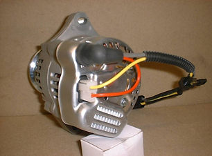
A rear shot of the Denso Alternator shows our 3 wire application. The Yellow wire being the circuit which is activated by 12V's in turn turning on the Voltage Regulator which is internally mounted. A simple 2 way Delphi plug is all that's needed to plug into any system. If you purchase one of our three wire Denso's, we supply the plugs to do so. The RED wire running to the output stud is the "voltage sense" wire which keeps tabs on the loads in the system. On small 12V conversion systems with low draw, this would work fine for the application. If a larger system is used, the RED voltage sense circuit could be run parallel with the output current circuit and remotely connected near the dash to monitor load used at a much busier dash area such as a "D" series Tractor.
With the Denso, you have the best of both worlds. Size & 3 wire universal hookup!
B&B TECH: Reverse Current Relays vs Voltage Regulators What's The Difference?
THE REVERSE CURRENT RELAY
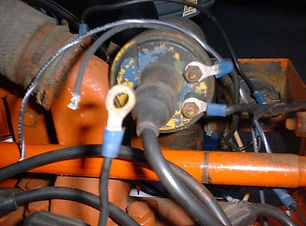
Most simple 6 volt wiring systems use a Reverse Current Relay or better known to the industry as a "Cutout" or "Cutout Relay". Okay, so what's its purpose and what does it look like? Well, glad you asked. A "Cutout" relay is the small box that usually sits on top of the Generator (6V or 12V) has two terminals out the front, and controls current flow to the Battery at times that Generator output is low. (usually at idle) Some folks mistake a cutout relay as a Voltage Regulator, but the cutout relay's only function is to sever the Battery from the Generator when the engine is either at a low idle or when the Tractor's engine is OFF. In most applications, the cutout relay is usually used in systems that utilize a resistor type light switch for voltage regulation. In most cases, if the cutout relay starts to malfunction, or the points inside get stuck together, the connection to the Battery is now closed, and the Generator can act as a Dynamo and slowly remove milivolts from the Battery has the Tractor sits. A good 6 volt Battery could be drained easily in a day or two giving you a dead Battery when the time comes to use the Tractor for chores again. The normal wiring to a cutout relay usually resides between the Ammeter's negative side (-) circuit to the cutout relays BAT terminal. The other terminal on the cutout relay which is the GEN (Generator) terminal runs to the "A" (Armature) post on the Generator. Pretty simple like the system. The "F" (Field) post on the Generator then runs to the resistor regulated charging switch to complete the charging circuitry. The Generators output is then controlled by the charging switch by increasing or decreasing the ground to the Generator. Low voltage is an enemy to the contacts in the cutout relay, so keeping the Battery up and in good condition is very important on a 6 volt wiring system for longevity.
VOLTAGE REGULATORS
Voltage Regulators do just that. Regulate voltage loads within the electrical system. Even though Voltage Regulators incorporate the "cutout" contact set inside the unit still, (which does the same job as the cutout) there's more to a VR than your basic simple "cutout relay". This is why a VR is larger in size than your basic cutout. In most cases, that's how a VR is distinguished from a cutout. Other recognizable examples would be the 3 or 4 terminals the VR has compared to just 2 terminals on the cutout. The VR will be a direct replacement of the resisted Headlight/Charging switch usually located in the instrument panel. Instead of you manually adjusting the charging rate going back to the Battery by pulling the switches knob in or out in its charging positions, the VR does that automatically, while monitoring the electrical systems voltage use and keeping the Battery happy. Looking at a Voltage Regulator's terminals, one can see the markings stamped in the terminals of how its connected into an electrical system. Markings on a 3 terminal VR are usually stamped: BAT (Battery) F or FLD (Field) and G or GEN (Generator) On a 4 terminal VR, there will be a fourth terminal marked L (Load) This terminal is usually used for any accessory such as powering up a Headlight switch or other switch that needs Battery power. In some applications, this terminal is not used and has no effect on the charging side of the system. Proper connections to a VR are as follows: BAT- from negative side (-) of Ammeter G or GEN- to "A" (Armature) post of Generator F or FLD (Field) to Field post on Generator. As I mentioned earlier, if your VR is equipped with an "L" (Load) terminal this may or may not be used depending on your application.
Note- if using the "L" terminal on your VR for an accessory, always make sure that the circuitry off the L terminal is fused! And that's it on VR's & Cutouts.
B&B TECH: A Guide To Automotive Wiring- Gauge Size, Loads, & Usage
AUTOMOTIVE WIRING GUIDE
When wiring anything Automotive, length and size of the wire used along with the load that wire has to carry is ultra important! Circuitry that carry heavy loads always have to be larger in size in order to handle that load and not cause "voltage drop". To light of a wire for the load it has to carry can cause some serious problems from wire failure to fires. The last thing you need in your car, truck, or Tractor is a fire! Below is a wiring guide to choosing the correct size wire for the load it needs to carry and also the length of the wire. As a rule of thumb, any circuitry that needs to carry current to a load item that is a ways from the Battery, should be upgraded to the next size gauge wire.
In 6V electrical systems, the wiring for the electrical system should be heavier than that of a 12V system, mainly because of the systems higher amperage. In most cases, the 6V systems wiring for the same function is usually one gauge higher in wire size than 12V. This guide is supplied by AC Delco. The wire sizes shown below for the lighting, power and instrument circuits, of normal length for the 6 volt and 12 volt electrical systems. Hope this helps you with your next project.
Automotive Circuits | Wire size 6 Volt | Wire size 12 Volt |
|---|---|---|
AMMETER TO CIGAR LIGHTER | 14 | 16 |
AMMETER TO SWITCH | 14 | 16 |
BACK UP OR WORK LIGHTS | 16 | 18 |
AIR CONDITIONER | 14 | 16 |
BATTERY TO SWITCH | 10 | 12 |
IGNITION COIL CIRCUITRY | 14 | 16 |
DIRECTIONALS OR FLASHERS | 14 | 16 |
AMMETER TO FUSE BLOCK | 10 | 12 |
DOME OR COURTESY LIGHTS | 16 | 18 |
ELECTRIC CLOCK | 16 | 18 |
HEADLIGHTS | 14 | 16 |
ELECTRIC WIPERS | 16 | 18 |
GAS GAUGE TO TANK | 16 | 18 |
GENERATOR TO AMP GAUGE | 10 | 12 |
Automotive Circuits | Wire size 6 Volt | Wire size 12 Volt |
|---|---|---|
HEATER | 16 | 18 |
HORN CONTACT | 14 | 16 |
HORN TO RELAY | 10 | 12 |
INSTRUMENT LIGHTS | 16 | 18 |
LICENSE LIGHT | 16 | 18 |
TAILIGHT CIRCUIT | 16 | 18 |
SPOT LIGHT | 16 | 18 |
STOP LIGHT SWITCH | 16 | 18 |
RADIO TO FUSE | 16 | 18 |
POWER WINDOWS | 16 | 18 |
PARKING LIGHTS | 16 | 18 |
LIGHT SWITCH TO FUSE | 12 | 18 |
CHARGE WIRES
The connection between the Generator or Alternator is very critical. An undersized charge wire or improper attached terminal wire could result in voltage loss or drop. When rewiring your Tractors electrical system, always make sure you use the proper size wire on the charging circuits. With Alternators, this is much more critical due to the fact Alternators come in a lot of different amperage sizes. Of coarse the higher the Alternator's output, the larger the charge wire should be. Below is another wire guide for the charging output. Remember, the larger the wire, the smaller the number!
AMPS | 4'-7' | 7'-10' | 10'-13' | 13'-16' | 16'-19' | 19'-22' | UP TO 4' |
|---|---|---|---|---|---|---|---|
35-50 | 12 | 10 | 10 | 10 | 8 | 8 | 12 |
50-65 | 8 | 8 | 6 | 6 | 6 | 6 | 10 |
65-85 | 8 | 8 | 6 | 6 | 4 | 4 | 10 |
85-105 | 8 | 6 | 4 | 4 | 4 | 4 | 8 |
105-125 | 6 | 4 | 4 | 2 | 2 | 2 | 6 |
175-200 | 4 | 2 | 2 | 0 | 0 | 0 | 4 |
150-175 | 4 | 4 | 2 | 2 | 0 | 0 | 4 |
125-150 | 6 | 4 | 2 | 2 | 2 | 2 | 6 |
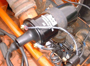
B&B TECH: "The Dead Mag Blues" Mag To Distributor Conversion From B&B!
Left- Our Mag to Distributor Conversion for the B,IB,C,CA & RC Tractors equipped with a Pertronix electronic ignition with the 125 engine.
How many times have you jumped up on your Tractor to head out to the fields or even want to attend a parade only to have the engine crank over but not start. Getting back down off the Tractor, you smell gas and say to yourself, well its getting gas. After checking out the Magneto, you find there isn't any spark. After messing around with the Mag for an hour or so, the spark at the Mag returns. For a short while anyway. And the Tractor dies again. These types of days equate to "lost time" days where you're spending more time under the hood of the Tractor to get it running than getting any work done or get a little play time in! Very aggravating to say the least!
Yeah, Mags are unreliable sometimes, especially if the Tractor sits outside with a tarp over it, or in a shed with a high moisture content. Whatever the circumstances, they can be a pain and make you tear your hair out. Don't get me wrong, when a Mag is working good and is "hot", they will run an engine all day long every day, and not miss a beat! But, when they get old and tired, they can be a bear, and expensive to repair. Well, we got the remedy for the old "Dead Mag Blues". A rebuilt top to bottom custom built Distributor and drive kit that comes with everything needed to change that old Mag Tractor over to a Battery Ignition Tractor! Say "NO" to Mags, and YES to Battery Ignition! Take that Tractor out of the 40's and put it in the 70's!
* Dependable & Reliable * Optional Electronic Ignition Available * Trouble Free Operation *
Our Distributor drive bolts right in place of where the Magneto attached. The same bolts can be used that held the Magneto on. Before you remove the Magneto, its always good to establish TDC (Top Dead Center) with number 1 cylinder on the compression stroke. Once that is established, you can now install the Distributors drive to the Govenor, and then mesh the Distributor into the drive. Start at number 1 cylinder and go around the firing order with our spark plug wires which are numbered for each cylinder. Install the supplied Autolite spark plugs in your engine for some new life when the engine lights up! After your new key switch that's supplied in this kit is installed along with our wiring and wiring instructions, you're ready to move into the "new age". Especially, if you ordered your Mag to Distributor conversion with a Pertronix ignition that we installed for you when your kit was being built. Whether equipped with points or our optional E.I., you'll be on the road to a more dependable and reliable ignition system! No more under the hood time! YES!!
Above- Our 201 & 226 engine conversion
When you order your new Mag to Distributor conversion kit, we will call you to go over what voltage system you will be running on your Tractor, also what model Tractor so we can make up the correct Spark Plug wire set for your model Tractor, along with fixing you up with the correct coil and wiring. If you want the optional E. I. , we'll fix you up with the correct kit you'll need for your conversion. We also set up each Distributor on our Distributor machine and run it for you to make sure everything is working according to the mfr's specifications, set the dwell so its ready to go when you get it. Here's what makes up a kit:
*Rebuilt Distributor Drive Assembly *Rebuilt Distributor *Choice of voltage Coil *Our HD Spark Plug Wire set *Autolite Spark Plugs *HD Ignition Key Switch *Full Ignition Circuitry *Installation Instructions * Coil Bracket *Distributor Hold Down Clamps *HD Copper Top Distributor Cap *New Distributor Base Gasket
Note: This is a Battery Ignition Kit. It is necessary to have a Battery and a Generator to keep the Battery charged to full peak performance! If you do not have a Generator, the Battery would need to be charged occasionally to keep the Battery at full charge in order to run this system. Give us a call with any questions you may have.
Get rid of the "Dead Mag Blues"! Order up a Mag to Distributor conversion from B&B Custom Circuits today!
B&B TECH: How To: Installing Our Custom Built Alternator Bracket Kit For B, IB, C & CA Model Tractors.

For those who own a Model B, IB, C or CA model Tractor that want to move up to a 12V conversion system, we offer just the system to bring those model Tractors from the 40's into the 80's with more modern technology and reliability. The 6V system is a very simple system and has been in service for decades, but that particular system needs a lot of TLC to keep it in tip top shape. An upgraded 12V system is an option for an owner who might have just purchased one of these model Tractors and needs to completely rewire the unit. Whether you want to stick with the OEM 6V system or upgrade to a 12V system, we got you covered either way! This little segment is about our optional Alternator bracket that we offer for those who want to upgrade to a 12V system. This kit works great for these particular model Tractors. Here's a little on this bracket...

For those who don't mind looking at an Alternator hanging off the side of the engine, then this bracket kit will work out quite nicely for those who prefer to go to a 12V system. Keep in mind, you can also move to a 12V Generator to keep the originality of the Tractor is still have a 12V system, but the cost factor will probably be more than moving to one of our 12V conversion kits.
Let's start with removing the old 6V Generator. Remove the top bracket adjusting bolt and remove the fan belt. You may have to loosen the lower anchor bolts to move the Generator toward the engine. Remove the upper adjusting bracket and re-install the nut and washer on the manifold stud. Remove the lower pivot bolts while supporting the Generator. Make sure you have a good grip on that Gennie, you don't want to drop it on your foot! That'll smart!
Once the Generator is removed, the OEM Generator bracket will be revealed as seen in the picture. Two 3/8" bolts hold the OEM bracket to the engine block. Once removed, we're ready to install our new Alternator bracket kit.
With the Generator out of the way, now is a good time to remove the water pump bolt that closest to you. This is where our new upper adjusting bracket will mount. Because that water pump bolt threads into the water jacket, you will probably experience some coolant when the bolt is removed. If your quick enough, you can install our bracket with the bolt going through it to where you won't loose much coolant. Snug up that bolt just enough to pivot the bracket.

Note: On model C & CA Tractors, depending on which Alternator you're using, the clocking, and the size, in some cases, approx. about an inch needs to be removed from our adjusting bracket and the 3/8" hole re-drilled for those models when using the "SI" series Alternator, due to the steering drag link that runs right through that area. Mock things up first before you cut! You might not need to do any alterations. We also offer the Denso pint size Alternator in the C & CA kits.
Mount our new bracket on the engine block with the new hardware supplied. Leave the bolts loose in order to get the final position the Alternator needs to be in at the end of the install. Okay, we're just about ready to install the Alternator. Don't forget to change the Generator pulley over to the Alternator. Let's keep rolling!
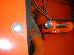
In this picture, you can see the clearance on our bracket from the lower coolant pipe. Quite a bit of thought went into this design. Not only are we supporting an Alternator, but because the Alternator is shorter than the OEM Generator, we had to raise the Alternator up over the lower coolant pipe and move it forward into a better position for belt alignment. With the bracket slotted at the mounting bolts to the engine block, this gives the installer plenty of room to move the Alternator forward or aft to position the Alternator right where it has to be for perfect alignment!
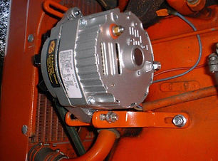
Set the Alternator in the mount and slide the lower pivot bolt through the Alternator into the rear bracket arm. Put the head of the bolt toward the Radiator to give clearance on the belt. This particular Alternator is a "10 SI" Delco which we supply with our complete 12V conversion kits. This bracket will also accommodate the "CS" series, & Denso pint size Alternators as well. Because this is a model B we're doing the install on, the "SI" series Altenators work great. On the C and the CA model Tractors the "CS" series Alternators come with our complete conversion kit. Install the top bolt in the adjusting bracket and leave loose. We're gettin' close here. Lets move on...NOTE: When using the Denso Alternators, because they are Metric, the lower bolt will be loose in the mounting hole. Not to worry. Once the unit is spaced properly and the anchor bolt tightened up, the Denso Alt will not budge.

Belts- When it comes to using the correct belt, there's a lot that needs to be taken into consideration. First the size and type of the Alternator used, the clocking of the Alternator, and whether there may be a loader or other PTO equipment off the crankshaft in the front of the engine. One belt doesn't fit all. The best way you can find out what belt you need if the OEM belt is a tad to short is position the Alternator where you want it to sit. Take a piece of clothesline rope or something similar and wrap it around the pulleys and the Alternator pulley and measure what you have. This will get you in the ballpark for the length belt you will need. Once the correct size belt is installed for your application, align the Alternator up perfectly using the belt as a guide and lock all the hardware up on the main bracket and adjusting bracket. The belt should look nice and straight and aligned perfectly with the engine pulleys as in the picture. If it looks like the pic, you did a great job! For those who chose to wire their own Tractor, we do offer several different plug in Alternator charging modules which you can plug right in and tie it in with your wiring. We supply the male/female plugs with each module kit.